
Material bars are made ready for processing on a lateral material storage facility (sloping surface). These are generally bars with round, hexagonal or quadratic outer contours, which may have either hollow or solid cross-sections and which may be made from a wide variety of materials. The bar diameters or key widths are in a range between approx. 1 and 100 mm.
In the case of loading magazines for “long bars”, the length of the bars generally varies between 1,600 and 6,000 mm. In special cases, FMB also offers solutions designed for the processing of much longer bars. The individual loading magazine models are offered by FMB in a number of standard variants for predefined lengths, intended to provide the best possible coverage of the range of material bar lengths commonly available on the market.
The lateral material storage not only holds the bars ready for processing, but also feeds a specified number of bars, in order to ensure the automated production of the required parts with as long an interval as possible between manual interventions.
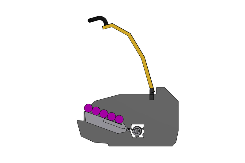
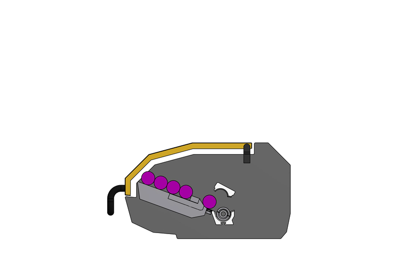
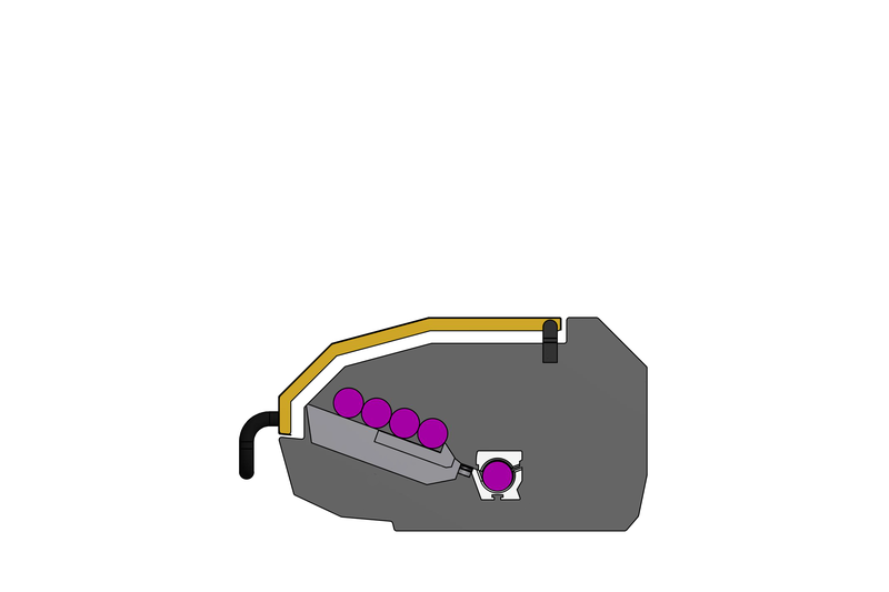
From this reserve in the magazine, the individual bars are separated out and deposited in a guide channel. From there the material bar is pushed by a pusher in the loading magazine, through the hole in the lathe spindle, where it is fixed in place on the spindle end next to the tool by a clamping device, usually a collet or a chuck. In principle, the diameter of the material bar to be processed also determines the diameter of the guide channels and thus also that of the pusher, which is guided in all positions within the loading magazine through the channel with a clearance of approx. 1 to 2 mm. The maximum usable guide channel diameter on a loading magazine corresponds to the maximum opening for the bars on the spindle stock of the lathe.

Once the bar is delivered, the turning process begins, during which the end of the bar is usually clamped in place for machining. The whole of the bar rotates during the turning process, as is the usual practice. The rotation speeds depend on the diameter of the material bar and at their peak can reach up to 15,000 rpm. On completion of the turning process, the collet or the chuck is released, enabling the loading magazine to push the material bar forward through the spindle by the required length of the part. After the bar is reclamped in place, the next processing cycle begins.
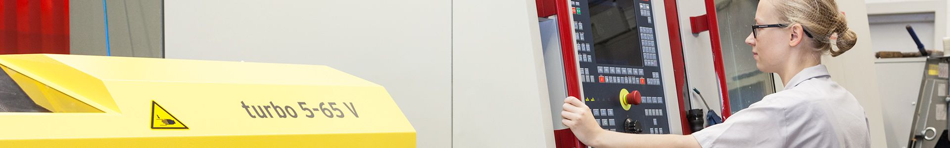
Ideally, the gap in the spindle stock of the lathe for passing the bars through must be adjusted to the diameter of the pusher, to enable it to provide optimum guidance. It is recommended that appropriate spindle liners are used if the diameter of the material bar to be processed means that a guide channel is selected which is smaller than the gap for passing the bar through on the lathe. Without this, the spindle hole would not accept the transfer from the pusher, when it pushes the material bar in from behind into the spindle stock in the next phase of the staged process. (Photo)
When processing “long bars”, if the original bar length is greater than the length of the spindle, part of the bar remains outside the lathe during the turning process and needs to be guided as it rotates. Depending on the lathe and the length of the loading magazine, this bar length can be 1,000 to 6,000 mm. In such cases the bar loading magazine not only needs to arrange and feed the material bars, but also needs to assume a guide function for the bars. A bar clamped at only one end by the collet of the lathe would naturally tend to swing out and create vibrations that would have a negative impact on the turning process, and in extreme cases could damage the whole system.
For this reason, it is necessary to take constructive measures to prevent such vibrations in the loading magazine. The overall structure of the loading magazine and corresponding design of the guide channel ensure that these vibrations are damped or prevented entirely. Channel inserts of various diameters are available for each loading magazine; these ensure guidance that is as free from vibrations as possible for a given material bar diameter range. In addition, the free end of the material bar is fixed to the freely rotating end of the pusher by a clamping sleeve or, for tubular material sections, a clamping mandrel. This also enables the material bar remnant pieces that inevitably result from the process to be drawn back into the loading magazine, where they are disposed of into a container. The optimum guidance of the bars themselves within the loading magazine is achieved by the “turbo principle”, developed and patented by FMB.
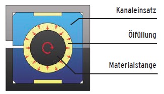
The guide channel is filled with oil by a pump assembly. Turbulence is created in the oil by the rotating material bar, enabling the bar to float. This prevents direct contact with the guide channel. With thinner material bars and high rotation speeds, an eddy current is generated and the material bar is guided in the centre of this. When processing thicker material bars, the diameter of which is close to the maximum gap, it is not possible for turbulence to be generated in the oil flow. In this case an effect known as the hydrodynamic bearing effect arises, whereby the liquid is formed into pressure cones, which keep the material bar in the centre of the guide channel.